
Step Functions To Plantuml
A look at asl-puml and how it emits a PlantUML state diagram from a AWS Step Functions json file. All the step functions I’ve implemented began as simple state diagrams in the PlantUML language. After implementing them as AWS Step Functions, it’s nice to be able to still view the actual process definition in the style from the original design document.
 |
PlantUML | Open source tool that provides a text based domain specific language for drawing diagrams |
 |
AWS Step Functions | A low-code, visual workflow service that developers use to build distributed applications |
Example diagrams
AWS Dynamodb example
The following process definition is from the AWS examples. It shows the use of DynamoDB to implement a semaphore. It doesn’t exercise a lot of different types of states but it’s a simple one to start with.
The one odd thing about this definition is that it contains two uses of a Parallel state with a single Branch. This is odd since you would expect multiple branches to be defined for a Parallel. The following is from a comment in the source:
Containing this in a parallel allows for visual separation when viewing the state machine and makes it easier to reuse this same logic elsewhere if desired.
This approach permits easier copy/pasting of this ASL across process definitions but that isn’t something I’d ever do. That leaves just the logical grouping of the states for display purposes. That’s not a strong enough use case to warrant a separate state in the definition. This is something best achieved outside of the process source.
Rendering in AWS Toolkit
- Good: shows the shape of the process
- Good: same rendering that’s used for executed processes in AWS console
- Bad: all of the states look the same so it’s hard to see what the behavior is
- Bad: no info on the state transitions so it’s difficult to see the fault handling
- Bad: uses an extra state to achieve logical grouping for display purposes.
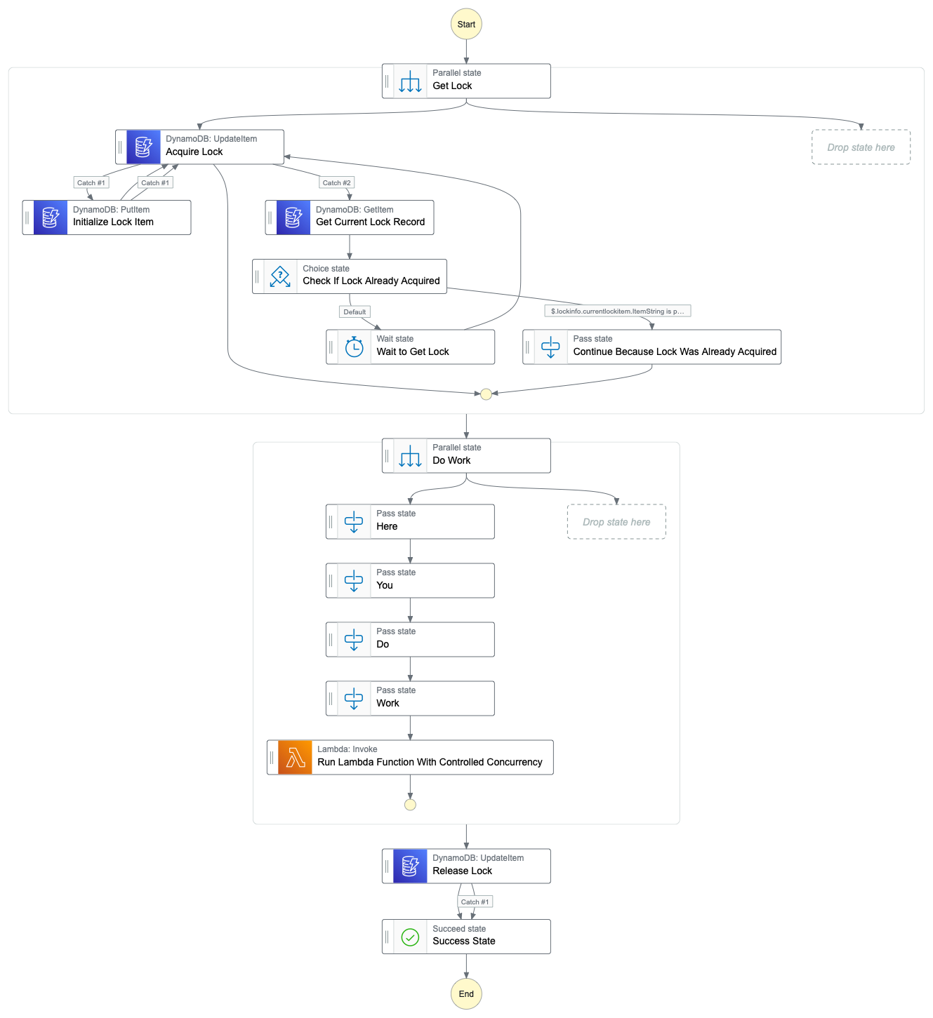
Rendering in AWS Studio
- Good: shows the shape of the process
- Good: conditional state transitions are labeled
- Good: catch transitions are labeled
- Good: uses icons, colors, and text labels to indicate the state type
- Bad: image shows prompts for new branches (artifact from the editor perhaps)
- Bad: not available outside of their editor
- Bad: uses an extra state to achieve logical grouping for display purposes.
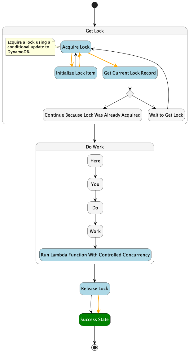
Rendering in asl-puml
- Good: shows the shape of the process
- Good: some conditional state transitions are labeled
- Good: catch transitions are #orange
- Good: uses icons and colors to indicate the state type
- Good: logical grouping of tasks for display and other settings via user supplied config
- Good: optionally displays comments from source
- Bad: not the same rendering as seen in the AWS Console for executed processes
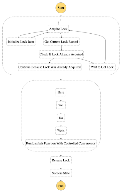
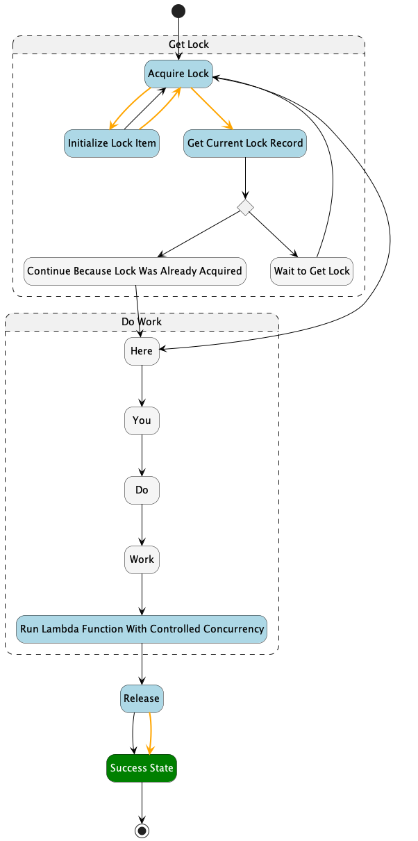
Example without the extra states:
Notice there are Get Lock and Do Work states but they are drawn with dotted lines. They are composite states introduced simply to support the logical grouping. This is done via the diagram’s config and doesn’t require additional states in the process definition.
Example showing some additional config options
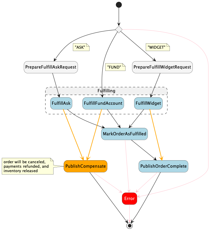
The above was generated with the following config:
{
  "theme": {
    "compositeStates": {
      "^Fulfill.+$": "Fulfilling"
    },
    "comments": {
      "^.+$": {
        "width": 30,
        "side": "left"
      }
    },
    "compensation": {
      "pattern": "^.*(compensate).*$",
      "color": "#orange"
    },
    "lines": {
      "fromCatch": {
        "bold": true,
        "color": "#orange"
      },
      "toFail": {
        "color": "#pink"
      }
    }
  }
}
compositeStates allows one or more regular expressions to control the logical grouping of states in the diagram.
comments allows one or more regular expressions to enable the rendering of a State’s Comment field.
compensation allows one or more regular expressions to mark a state as being part of the compensation workflow. This is important for step functions that have cleanup to do in the case of a fault.
lines allows styling transitions from a caught error or to a fail state. This helps convey the error handling of a process.
Next steps
I like the code coverage report I get for my Typescript code with Jest and would like something like this for my step functions as well. The executed state machines are available in the emulator so it seems possible to produce a single diagram that showed the covered paths and drew attention to the uncovered paths.